This audit checklist verifies PLC integration and safety interlocks before robot startup. It covers control logic, hardware connections, and emergency stop paths. Use it to confirm that safety systems function correctly and prevent hazardous movements.
- Verify every safety input and output path between the robot and PLC before energizing the system.
- Test emergency stop circuits and safety relays to confirm they cut power to the robot.
- Confirm that the PLC and robot share the same coordinate system and communication protocol.
- Check physical interlocks such as doors and light curtains to ensure they prevent movement.
- Document all test results to create a verifiable audit trail for compliance.
Why Pre-Commissioning Checks Matter
Robot integration fails at the boundary between the motion controller and the logic controller. The PLC handles the sequence. The robot executes the motion. If the interlock logic is wrong, the robot can move into a restricted zone or ignore an emergency stop.
This checklist covers the core checks for PLC integration and safety interlocks. It is designed for engineers and commissioning teams verifying the system before startup.
The failure mode is rarely dramatic. It is often subtle. A safety input card receives a signal from a door switch, but the wiring is reversed. The PLC reads a “closed” state when the door is actually open. The robot enables. An operator walks into the work cell. The result is a catastrophic incident.
Pre-commissioning checks exist to catch these errors before the system is handed over. They are not administrative formalities. They are the last line of defense against design or installation errors. The checks below verify that the electrical, logical, and physical layers of the system function as intended.
Control Logic and Program Structure
Start with the PLC program structure. The robot should only receive motion commands when all safety conditions are met.
- Verify the Safety Input Map. List every safety input in the PLC. Map each physical device, such as a light curtain or door switch, to a specific input channel. Confirm the input state matches the physical device state.
- Practical Example: Open the PLC software and navigate to the I/O map. Select the input for the light curtain on the north side of the cell. Physically break the beam by walking through it. The PLC status should change to “0” or “Open.” If it remains “1,” the wiring is reversed or the input card is faulty.
- Check the Safety Output Logic. Identify which outputs control the robot enable and safety relay. The PLC should only output a “safe” command when all safety inputs are active.
- Practical Example: Look at the logic rung that drives the robot enable output. It must include a series logic chain of all safety inputs. If you remove the door switch from the chain, the robot should not enable.
- Review the Interlock Sequence. Trace the logic for how the robot is enabled. The PLC should require specific conditions, such as a door closed and a light curtain unbroken, before sending a robot enable signal.
- Practical Example: Check if the program uses a single “safe” bit or individual bits. If it uses a single bit, verify that bit is driven by the AND of all safety inputs.
- Test the Reset Path. Verify how the safety system resets after a fault. The reset should require a deliberate operator action, not an automatic reset.
- Practical Example: Break a light curtain. The robot should stop. Remove the object. The robot should not restart. The operator must press the reset button on the control panel.
Red Flag: The PLC program uses a single generic “safe” bit that is not tied to specific safety inputs. This makes it hard to diagnose which device caused a fault. If a fault occurs, you will see the “safe” bit is low, but you will not know if it was the door, the light curtain, or the E-stop that tripped it.
Hardware Connections and Wiring
Wiring errors cause intermittent faults that are hard to trace. Check the physical connections before powering the PLC.
- Inspect Safety Cable Routing. Ensure safety cables are routed separately from power cables to reduce noise. Check for pinched or damaged insulation.
- Practical Example: Run your hand along the cable tray. Safety cables should be in a separate section of the tray or at least separated by at least 10 cm from high-voltage power cables. If you see insulation chafing against a sharp edge, replace the cable.
- Verify Terminal Connections. Open the terminal blocks and confirm each wire goes to the correct pin. Use a multimeter to check for continuity and short circuits.
- Practical Example: Pick a wire labeled “Door Switch 1.” Trace it from the door to the terminal block. Verify it is connected to the correct pin. Then, with power off, use a multimeter in continuity mode to check that the wire is not shorted to an adjacent pin.
- Check Grounding. Verify the safety circuit ground is connected to the main ground bus. A floating ground can cause false faults.
- Practical Example: Locate the ground terminal block on the PLC. Verify that the shield of the safety cable is connected to this block. Also, verify that the robot chassis ground is connected to the same reference point.
- Inspect Safety Relay Coils. Confirm the safety relay is the correct type and rated for the load. Check that the coil voltage matches the PLC output voltage.
- Practical Example: Check the nameplate on the safety relay. If the PLC outputs 24 V DC, the relay coil must be rated for 24 V DC. If it is a 12 V relay, it will not function correctly.
Red Flag: Safety wires are twisted together with power wires. This introduces noise that can cause the PLC to see false inputs. Intermittent faults are a hallmark of this wiring error.
Emergency Stop and Safety Relay Path
The emergency stop path is the last line of defense. It must cut power to the robot immediately, independent of the PLC program.
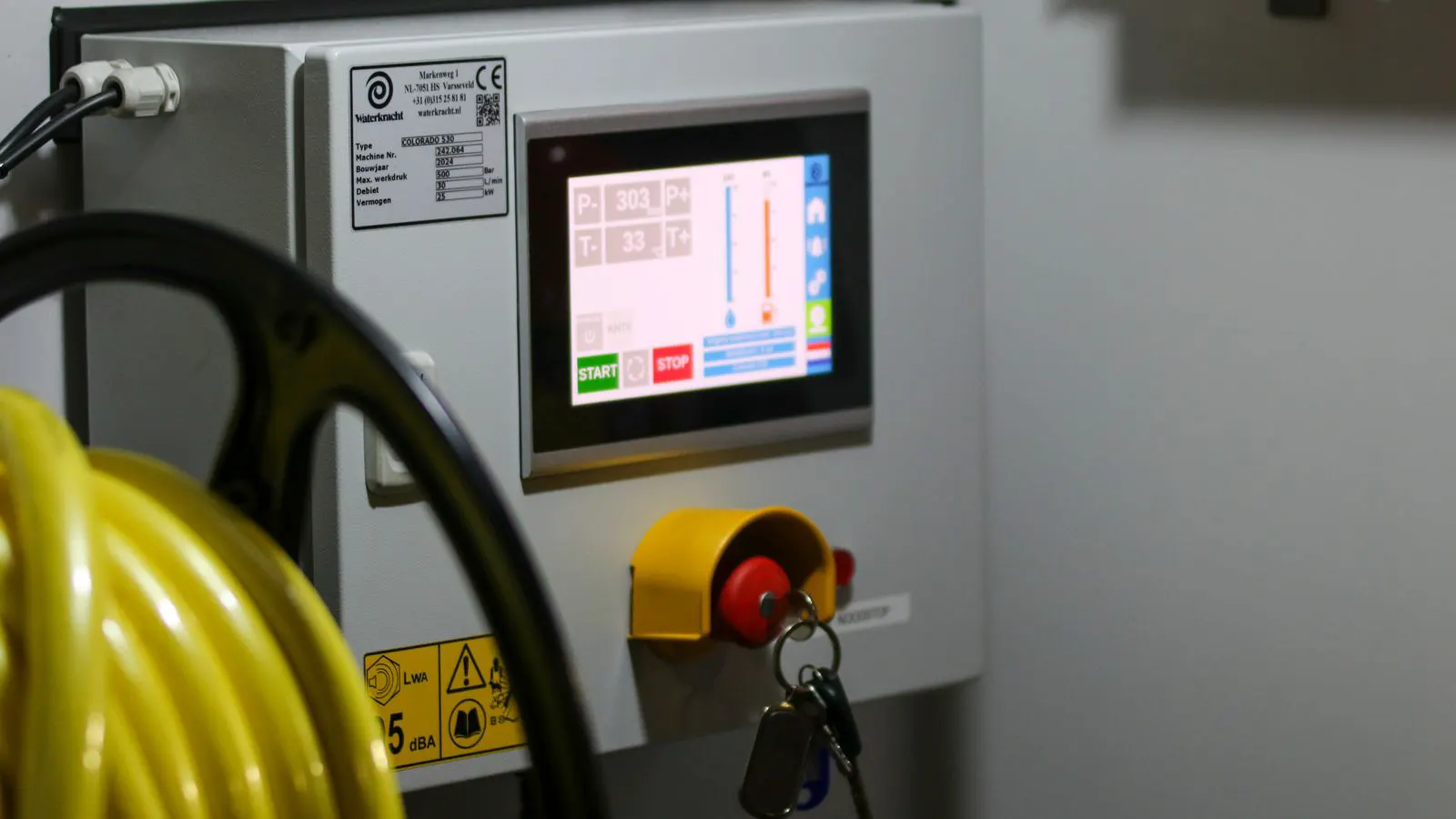
- Test the Emergency Stop Button. Press the E-stop and verify the safety relay de-energizes. The relay should drop its output contacts.
- Practical Example: With the system powered, press the E-stop button. Listen for the relay click. The relay status light should go off. The robot should stop immediately.
- Verify Power Cut-Off. Confirm the robot servo power is cut when the safety relay de-energizes. Use a multimeter to check for zero voltage at the robot power input.
- Practical Example: With the E-stop pressed, place your multimeter probes across the robot power input terminals. The reading should be 0 V. If there is still voltage, the safety relay is not cutting the power.
- Check the Safety Relay Output. Measure the voltage across the safety relay output contacts. They should be open when the relay is de-energized.
- Practical Example: Check the relay output contacts that feed the robot enable signal. With the E-stop pressed, the contacts should be open. Measure the voltage across them. You should see the full supply voltage, indicating the circuit is open.
- Test the Reset Circuit. Verify the reset switch is wired in series with the safety relay coil. The relay should not re-energize until the reset switch is pressed.
- Practical Example: Release the E-stop. The relay should remain de-energized. Press the reset button. The relay should re-energize. If the relay re-energizes without pressing the reset button, the reset circuit is faulty.
Red Flag: The E-stop button is wired in parallel with the safety relay coil. Pressing the E-stop will not cut the relay power. This is a critical safety failure.
Communication and Data Integrity
The PLC and robot must exchange data without error. Check the communication protocol and data mapping.
- Verify Communication Protocol. Confirm the PLC and robot use the same protocol, such as Ethernet/IP, PROFINET, or serial. Check the baud rate and IP address settings.
- Practical Example: Open the PLC configuration software. Check the IP address of the robot controller. Verify it matches the robot’s actual IP address. Check the subnet mask. Ensure both devices are on the same subnet.
- Check Data Mapping. Confirm the PLC writes the correct data to the correct robot memory locations. A wrong address can cause the robot to execute the wrong motion.
- Practical Example: Check the mapping table in the PLC program. The “Robot Enable” bit in the PLC should map to the correct bit in the robot’s I/O table. If the mapping is off by one bit, the robot might receive an enable signal when it should not.
- Monitor Communication Health. Use the PLC diagnostic screen to check for communication errors or timeouts. Any errors indicate a wiring or configuration issue.
- Practical Example: Open the PLC diagnostic screen. Look for the “Communication Status” or “Network Health” indicator. It should show a stable connection. If it shows intermittent errors, check the Ethernet cable and switch ports.
- Test Data Integrity. Send a test command from the PLC and verify the robot executes it correctly. Check the robot status feedback to confirm the command was received.
- Practical Example: Use the PLC ladder logic to write a test command to the robot, such as “Move to Point 1.” Verify the robot executes the move. Then, check the robot status feedback. It should indicate that the command was received and completed.
Red Flag: The communication link drops intermittently during testing. This suggests a loose connector or a wiring fault. Intermittent communication errors can cause the robot to stop unexpectedly, leading to production downtime.
Safety Devices and Physical Interlocks
Physical devices such as light curtains and doors must prevent the robot from moving into a restricted area.
- Test Light Curtain Alignment. Align the light curtain emitters and receivers. Verify the beam is unbroken when the area is clear and broken when an object is inserted.
- Practical Example: Look at the light curtain status light. It should be green when the area is clear. Walk through the beam. The light should turn red or off. The PLC should detect this change. If the light remains green when you walk through, the alignment is wrong.
- Check Door Interlock Switches. Press the door interlock switch. Confirm the PLC sees the door as open. The robot should disable motion when the door is open.
- Practical Example: Open the safety cage door. The PLC should show the door input as “Open.” The robot should stop. Close the door. The PLC should show the door input as “Closed.” The robot should be able to enable.
- Verify Guarding Integrity. Inspect the safety cage or fence. Ensure all panels are locked and no gaps allow an operator to reach the robot.
- Practical Example: Walk around the work cell. Check that all panels are securely fastened. Check that the fence height is sufficient to prevent an operator from climbing over. Check that there are no gaps larger than 10 cm.
- Test the Safety Zone. Activate the safety zone and verify the robot stops when an object enters the zone. The stop should be immediate.
- Practical Example: Use a safety zone monitor. Place an object in the zone. The robot should stop immediately. Remove the object. The robot should not restart until the safety zone is re-enabled.
Red Flag: The light curtain beam is misaligned. The PLC sees the beam as broken even when the area is clear, causing false faults. This is a common installation error.
Documentation and Audit Trail
A complete audit trail is required for compliance and future maintenance. Document every check and result.
| Check Item | Status | Notes |
|---|---|---|
| Safety Input Map | Pass | All inputs verified |
| Safety Output Logic | Pass | Logic confirmed |
| E-Stop Path | Pass | Relay cuts power |
| Communication Health | Pass | No errors detected |
| Light Curtain | Fail | Beam misaligned |
| Door Interlock | Pass | Switch works correctly |
Red Flag: Missing documentation. If a fault occurs later, you will not be able to trace the issue. A signed-off checklist is the proof that the system was tested. Without it, you are relying on memory, which is unreliable.
Final Verification Before Startup
Before allowing the robot to run in normal mode, perform a final check.
- Run the Safety Test Sequence. Activate each safety device one by one and verify the robot stops.
- Practical Example: Break the light curtain. The robot stops. Close the door. The robot stops. Press the E-stop. The robot stops. This sequence verifies that all safety devices are functional.
- Verify the Enable Sequence. Confirm the robot only enables when all safety conditions are met.
- Practical Example: Ensure the door is closed, the light curtain is unbroken, and the E-stop is not pressed. Then, press the start button. The robot should enable.
- Check the Alarm Log. Review the PLC alarm log for any unresolved faults.
- Practical Example: Open the PLC alarm history. Look for any alarms that are still active. Clear any false alarms. If there are real alarms, resolve them before startup.
- Sign Off on the Checklist. Have a second engineer review the checklist and sign off.
- Practical Example: A second engineer should review the completed checklist. They should verify that all checks were performed and that the results are accurate. Their signature is the final approval to start the robot.
Red Flag: The checklist is signed off without testing the E-stop path. This is a major safety risk. The E-stop path is the most critical safety function. It must be tested.
Common Mistakes to Avoid
- Using the Wrong Safety Relay. A standard relay will not cut power quickly enough. Use a safety-rated relay.
- Explanation: Standard relays do not have the built-in verification and testing features required for safety circuits. They can fail silently. A safety relay is designed to detect internal faults and de-energize itself if a fault is detected.
- Ignoring Noise. Poor wiring can cause false faults. Use shielded cables and proper grounding.
- Explanation: Electrical noise from power cables can interfere with safety signals. This causes false faults. Shielded cables and proper grounding reduce this noise.
- Skipping the Reset Test. If the reset path is wrong, the system will not recover from a fault.
- Explanation: If the reset path is faulty, the system will remain in a fault state. This causes downtime. It also indicates a potential safety issue.
- Not Testing the Light Curtain. A misaligned beam causes false faults and can allow the robot to move into a restricted zone.
- Explanation: A misaligned light curtain does not detect an object entering the zone. This is a direct safety hazard.
- Missing Documentation. Without a record, you cannot prove the system was tested safely.
- Explanation: Documentation is required for compliance. It is also essential for maintenance. Without it, you cannot trace the history of the system.
When to Call for Support
If you encounter a fault that cannot be resolved with this checklist, contact the robot manufacturer or a certified integrator. Do not bypass safety devices to get the system running. A temporary bypass is a permanent risk.
Bypassing safety devices is a common mistake under production pressure. It creates a false sense of security. The system is not safe. If a fault occurs, the safety devices are not there to protect the operator. This is a serious liability. If you cannot resolve the fault, stop the system. Contact support. Do not take shortcuts.
Frequently asked questions
How do I verify the safety relay cuts power to the robot?
Use a multimeter to measure the voltage at the robot power input. When the E-stop is pressed, the voltage should drop to zero.
What is the difference between a safety input and a standard PLC input?
A safety input is part of the safety chain and must be verified for integrity. A standard input is used for normal control logic.
How often should I test the light curtain?
Test it during pre-commissioning and after any maintenance. A routine inspection should be performed regularly to ensure the beam remains aligned.
Can I use a standard relay for the safety circuit?
No. Use a safety-rated relay that is designed to cut power quickly and reliably. Standard relays may not meet safety standards.
What should I do if the communication link drops?
Check the wiring and connectors. Verify the IP address and protocol settings. If the issue persists, check the network hardware.