A teach pendant records the robot's physical position, speed, and acceleration into numerical data that the controller compiles into executable code. This direct translation means the initial manual path is the final programmed motion. Understanding this link helps buyers plan integration, review safety limits, and select the right controller for their production cell.
- A teach pendant captures actual mechanical position data, not just abstract coordinates, which directly affects the final programmed path.
- Manual teaching speed and acceleration settings become hard limits in the generated program until explicitly changed.
- Integration teams must verify that pendant-set parameters align with production requirements and safety standards before commissioning.
How the Pendant Records Motion
A teach pendant is the physical interface used to move a robot manually during setup. It is not just a remote control. It is a data collection tool that feeds precise positional and kinematic values directly into the robot controller.
When an operator holds the pendant and moves the robot arm through a work cycle, the controller calculates the exact joint angles, linear velocity, and acceleration at every moment. This raw data becomes the source material for the program. The pendant does not guess the path. It records what actually happened.
This distinction matters for sourcing decisions. Some controllers handle pendant data with high resolution and fast sampling rates. Others use simpler interpolation between key points. The difference affects how smooth the final motion feels and how accurately the robot tracks its programmed path.
A high-resolution system captures the continuous arc of a hand motion. If you sweep your wrist to guide the end effector around a curved fixture, the controller logs dozens of points per second. A lower-resolution system might record only the start and end of that sweep and calculate a straight line or a basic arc in between. The first method preserves the operator intent. The second method simplifies it.
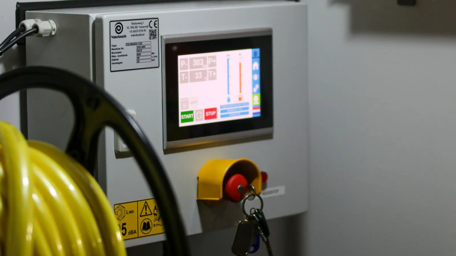
The physical build of the pendant matters here. Heavy joysticks with detents help the operator hold a steady position. Fine-grained thumbwheels allow precise orientation changes. A pendant with a screen that displays real-time joint values helps the operator see if the arm is approaching a limit. Without this feedback, the operator is working blind, and the recorded data reflects hesitation or over-correction.
From Manual Movement to Code
The transition from manual teaching to executable code follows a strict sequence. First, the operator defines waypoints by moving the robot to specific positions. Second, the pendant stores these positions in the program memory. Third, the controller translates those stored values into a sequence of motion commands.
Each recorded point includes more than just x, y, and z coordinates. The data captures joint positions, tool orientation, and the specific speed profile used to reach that point. When the program runs, the controller replays this exact data.
This process is why a poorly executed manual teach can cause problems later. If the operator moves too fast through a tight corner, the generated code will attempt to replicate that rapid transition. The result can be vibration, poor part placement, or even a collision.
Consider a robot picking a small screw from a tray. The tray has raised dividers. The operator uses the pendant to lower the gripper into the tray. If the operator moves the pendant too quickly, the end effector might hit the divider. The controller records the collision as a stop or a deviation, depending on the safety settings. If the program is saved without fixing this, the robot will hit the divider every single cycle.
The code generation step is where the controller applies its specific logic. Some systems insert linear interpolation between waypoints. Others use spline interpolation to smooth the transition. If you place two waypoints close together, a linear interpolation creates a sharp turn. A spline interpolation rounds that corner. The pendant records the positions, but the controller decides how the robot moves between them. This decision impacts the mechanical load on the arm. Sharp turns require higher torque and can excite natural frequencies of the arm, leading to oscillation.
The Role of Speed and Acceleration
Speed and acceleration settings on a teach pendant are often overlooked, but they define the motion character of the entire program. These values are not just suggestions. They become the baseline for every programmed segment.
When you set a speed of 50 percent on the pendant, the controller uses that value for the motion between points. If you do not change it, the final program runs at 50 percent. This directly impacts cycle time. A slower manual teach means a slower production cycle unless the programmer adjusts the values afterward.
Acceleration controls how quickly the robot reaches or stops at its target speed. High acceleration produces snappy motion but increases mechanical stress. Low acceleration is smoother but adds to cycle time. The pendant sets these values, and they must be reviewed during integration to match the production requirements and the mechanical limits of the robot.
Acceleration is a vector quantity. It applies to both the start of a move and the stop. A high acceleration at the start means the robot reaches its target speed quickly. A high acceleration at the stop means it decelerates rapidly. In a pick-and-place application, high deceleration is often required to stop the gripper precisely above a part. If the deceleration is too low, the robot overshoots the target. If it is too high, the vibration can dislodge the part.
The pendant often has separate buttons or sliders for speed and acceleration. Some systems allow you to set these per axis. Others use a global setting. Global settings are easier to manage but less flexible. Per-axis settings allow the programmer to tune the motion for specific joints. For example, the base joint might require lower acceleration to reduce the load on the foundation, while the wrist joints can handle higher acceleration because they have less mass to move.
Integration Implications
Understanding how pendant data drives motion changes how integration teams plan their work. The manual teach phase is not just a setup step. It is the first draft of the program.
Buyers and engineers should treat the pendant as a critical integration tool. The data recorded during this phase determines the baseline for all subsequent programming. If the manual path is inefficient, the programmed path will be inefficient. If the manual speed is too high, the programmed speed is too high.
This creates a clear sourcing decision point. When evaluating robot controllers, look at how they handle pendant data. Some systems allow for easy review and modification of recorded data. Others make it difficult to see what was actually recorded during the manual teach. The former reduces integration time and the risk of hidden errors.
A good controller interface shows the recorded path on a 3D model. It displays the waypoints and the interpolation type. It lists the speed and acceleration values for each segment. If the interface only shows the final code, the team must reverse-engineer the settings. This takes time and increases the chance of error.
During the sourcing phase, ask the vendor how the pendant records motion. Does it log every move? Does it allow you to replay the motion at different speeds to check for collisions? Can you export the recorded data to a CSV file for analysis? These features determine the ease of integration and the quality of the final program.
A practical example involves a palletizing cell. The robot moves from a conveyor to a pallet. The operator uses the pendant to define the pick and place points. The path between the points is a long arc. If the controller records this as a straight line, the robot will swing through the air in a way that might hit a nearby fixture. If the controller records the arc, the robot follows the operator’s intended path. The ability to see and edit this path before saving is a key differentiator.
A Worked Example
Consider a pick-and-place cell where a robot moves from a bin to a conveyor. The operator uses the teach pendant to move the robot arm from the bin position to the conveyor position. During this move, the operator holds the speed at 30 percent to ensure a clean path.
The pendant records this 30 percent speed and the specific acceleration profile used. Later, when the programmer reviews the code, they see this 30 percent value. If the production requirement is 60 percent, the programmer must change the value in the program. If they forget, the cell runs at 30 percent, reducing output.
This example shows the direct link between manual teaching and final performance. The pendant does not just move the arm. It writes the code.
In this scenario, the operator also sets the acceleration to a medium value. This is a compromise between speed and smoothness. The programmer reviews the code and sees the medium acceleration. They decide to increase it to a high value for the horizontal move between the bin and the conveyor. This reduces the cycle time by a few seconds. However, they must test this change at low speed first. If the high acceleration causes the arm to vibrate, they must revert to the medium value.
The key is that the pendant data is a starting point, not a final answer. The programmer must review every value. A single misplaced decimal or a forgotten speed change can ruin a program. The integration team must have a process for verifying pendant data against production requirements.
Common Mistakes in Manual Teaching
Several mistakes arise from not understanding how pendant data works. The first is teaching at maximum speed. Operators often rush the manual teach to save time. This creates a program with high speed and acceleration values that may not be safe or accurate.
The second mistake is ignoring the acceleration settings. A fast move with low acceleration can cause the robot to stall or vibrate. A fast move with high acceleration can cause mechanical wear. The pendant settings must be checked, not assumed.
The third mistake is not documenting the pendant settings. If the operator changes speed or acceleration during the teach, those changes are recorded. If the team does not know what was changed, debugging becomes difficult. Keep a log of all pendant adjustments during the manual teach phase.
A fourth mistake is not using the safety envelope correctly. The pendant has a speed limit, but it also has a position limit. The operator might move the arm to a position that is within the robot’s range but outside the safety envelope. The pendant allows this move, but the programmed path will violate the safety limit. The operator must check the safety envelope during the teach, not just the robot’s range.
A fifth mistake is not clearing the path of obstacles. The operator might move the arm through a path that is clear during the teach but will be blocked by a part during production. The pendant records the path, but it does not know about future obstacles. The operator must mentally map the production environment and ensure the path is clear.
Verifying the Program
Before commissioning, the integration team must verify that the programmed motion matches the intended path. This involves running the program at low speed and watching the robot track the path.
Check the joint positions in the program code against the recorded pendant data. If there are discrepancies, the manual teach may have been interrupted or modified. Review the acceleration and speed values to ensure they match the production requirements.
Finally, test the program under load. The robot may move smoothly without a part, but it may vibrate or drift when it is holding weight. The pendant data was recorded without load, so the programmed motion may need adjustment for real-world conditions.
Verification includes a visual check and a data check. The visual check involves watching the robot move. Look for any jerky motion, overshooting, or drifting. The data check involves opening the code and comparing the values to the pendant log. If the code says 50 percent speed but the pendant log says 60 percent, there is a mismatch. This mismatch can cause the robot to move faster than expected, leading to a collision.
Under load testing, the robot holds a part of the same weight as the production part. This part is placed in the gripper during the teach. If the part is too light, the robot will move differently than it will with the real part. If the part is too heavy, the robot may not be able to handle it. The load test should use the actual part or a replica of the same weight and dimensions.
Safety and Interlocks
Teach pendant data also affects safety. If the manual teach path includes a position that is too close to a human operator or a fixture, the programmed path will follow that same path.
During integration, review the recorded positions against the safety envelope. Adjust the path in the program if necessary. Do not rely on the pendant path to be safe. The pendant records what you do, not what is safe.
Refer to the pre-commissioning checklist for PLC robot interlocks to ensure that the programmed path does not violate any safety limits. The pendant data drives the motion, but the safety system must independently verify that the motion is allowed.
The safety envelope is a virtual boundary around the robot. It defines the area where a person can stand. If the programmed path enters this area, the safety system must stop the robot. The pendant data is used to define this path. If the pendant data is wrong, the safety envelope is wrong. The integration team must verify the safety envelope against the actual layout of the cell.
Interlocks are electrical or software switches that stop the robot when a condition is met. For example, a door switch on the enclosure is an interlock. If the door opens, the robot stops. The pendant data does not control interlocks. The interlock logic is defined in the PLC. However, the pendant data determines when the robot is moving. If the robot is moving when the door opens, the interlock must stop it. The integration team must test this interaction. They must move the pendant to start the robot and then open the door. The robot must stop immediately. If it does not, the interlock logic is flawed.
The final check is a full run with the safety system active. The robot runs the program at full speed. The safety system monitors the path and the interlocks. If everything works, the program is ready for production. If not, the team must fix the issues. The pendant data is the foundation. If the foundation is weak, the building will collapse.
Frequently asked questions
Does a teach pendant only record x, y, and z coordinates?
No. It records joint angles, tool orientation, speed, and acceleration. This full data set defines the programmed motion.
Can I change the speed after teaching the path?
Yes. The programmed speed can be modified in the code. However, the initial pendant setting becomes the default value until changed.
What happens if I teach a path too fast?
The program will attempt to replicate that fast motion. This can cause vibration, poor accuracy, or a collision. Review the speed settings during integration.
Is the manual teach path the same as the final program?
Yes, the manual teach path is the baseline for the final program. Any changes must be made in the code after the manual teach.
How does the pendant affect sourcing decisions?
The controller's ability to record and display pendant data affects integration time and error detection. Choose a controller that makes it easy to review recorded data.